TT Power System. One point directly earthed
Integrated
Bindery Systems
IBIS website  search
| Smart-binder/SLB floor plan | View |
| Floor loadings | View |
| Electrical power supply requirements | View |
| Compressed air supply requirements | View |
| Factory air conditioning | View |
| Trimmer waste (trim-off) removal systems | View |
| Smart-binder machine unloading from the delivery truck | View |
| Machine module approxiate weights and sizes (crated) | View |
| Smart-binder Module Weights and Sizes (uncrated) | View |
| Connection to upstream equipment | View |
| Smart-binder log-files, diagnostics and connection to external MIS systems | View |
| Installation planning | View |
| Planning for Smart-binder consumables supply | View |
View SB/SLB floorplans that include side -view dimensions and SB with other modules on webpage Full SB floor plan
The Smart-binder/SLB and other optional modules (sheet pile feeder, buckle folder, stacker etc) are supported on a number of feet, typically 70mm (2.75") in diameter. The maximum foot load (below the Smart-binder) is approximately 500kg/1100lb (most feet loads are much lower). If you plan to install the Smart-binder and modules on a floor with limited load-bearing capacity please Contact IBIS to discuss.
Total Smart-binder/SLB machine weight 1900 kg (4200 lb).
During installation the machine is moved on wheels which can apply more concentrated loads than those listed here. This is not usually a problem but can make machine alignment and movement on soft floor surfaces difficult.
Swipe columns to left to view all the table.
| Equipment | Model | Phases | Rated voltage (V) |
Rated current (A) |
Recommended supply (A) (note 1) |
Operation from 208/220/480V supply |
|---|---|---|---|---|---|---|
| Smart-binder | SB2, SB3, SLB | 3+N | 400 | 16 | (US)15 / (EU)16 | TFR-100 (note 3) |
| Sheet Pile Feeder | SB-095 | 3 | 400 | 5 | (US)15 / (EU)16 | TFR-100 (note 3) |
| SB-097 | 3+N | 400 | 6 | (US)15 / (EU)16 | TFR-100 (note 3) | |
| Sheet Folder | F-100 | 3 | 400 | 3 | 16 | Specify voltage when ordering |
| F-100 | 3 | 208 | 6 | 15 | ||
| Booklet Stacker | BSS-10 | 2 | 208-440 | 6-3 | (US)15 / (EU)16 | Refer to note 2 |
Notes:
Consult IBIS if input voltage is not in the ranges listed above.
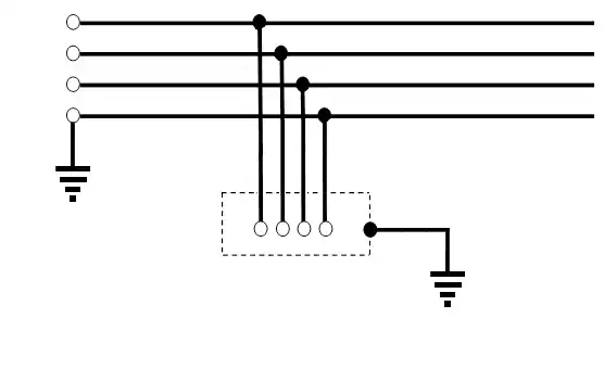
TT Power System. One point directly earthed
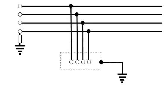
IT Power System. No direct connection to earth
Swipe columns to left to view all the table.
| Equipment | Model | Pressure Bar |
Pressure PSI |
Consumption Liter/min |
Consumption CFM |
Maximum Flow Liter/min |
Maximum Flow CFM |
|---|---|---|---|---|---|---|---|
| Smart-binder | SB2, SB3, SLB | 6.2 | 90 | 50 | 1.8 | ||
| Stacker | BSS-10 | 0.55 | 80 | 45 | 1.6 | 76 | 2.7 |
The BSS-10 stacker requires large but intermittent air-flow. Supply pipework must accommodate the maximum flow.
The Smart-binder environment should be controlled to reduce variability in the behaviour of the paper. This should result in more consistent, reliable operation.
Maintain relative humidity within the range 40-60% and temperature between 18 and 25ºC (64 and 77ºF).
Heat output when running
| Equipment | Model | Running Heat Output | |
|---|---|---|---|
| (kW) | BTU/hr | ||
| Smart-binder | SB2, SB3, SLB | 6.7 | 22860 |
| Sheet Pile feeder | SB095 | 2.5 | 8530 |
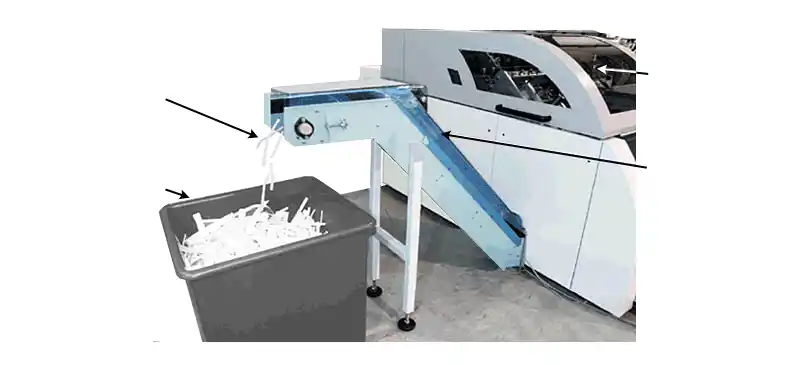
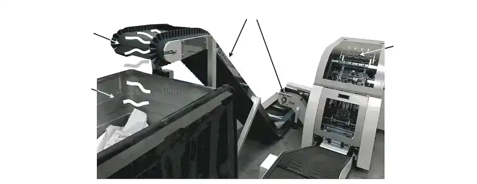
If the installation site has a pneumatic (vacuum) paper extraction system then it is recommended that this is used to remove waste paper from the Smart-binder trimmer. The optional Smart-binder trimmer waste collection chute TCC-100 (part B0001944: see below) may be supplied to connect to the external extraction pipe.
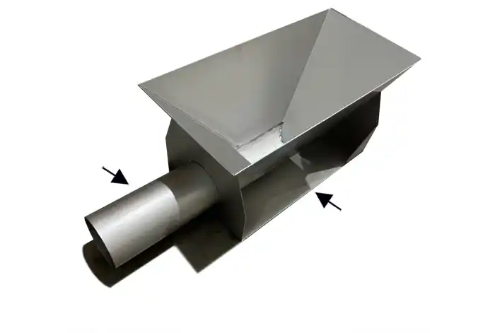
Alternatively, the optional Trimmer waste removal conveyor (TWC-100 or TWC-101 as shown below) can be supplied to convey trimmed paper trim-off to a collection bin
Al machines will be delivered on wooden pallets, and either covered or wooden-crated, depending on whether the machine is transported by sea/air or only by road. See below for dimensions and weights of these crates.
A fork lift truck capable of lifting 2.5 Tons (2500kg / 5500lb) is required for lifting the largest module of the Smart-binder off the base of the crate and into position. Its forks must be at least 1.5m (59”) long (requires fork extensions).
Each module has castor wheels for easy positioning and screw pads for final location.
See below for dimensions of the largest unit. Ensure that doors, etc. are large enough for this module.
The basic in-line Smart-binder SB2, SB-3 or SLB is delivered in 4 separate wooden
crates.
Note: if exact weights and dimensions are needed then information should
be obtained from IBIS at the time the machine is shipped.
| Crate | Size (L x W x H) | Weight | ||
|---|---|---|---|---|
| Cm | Inches | Kg | Lb | |
| 1 | 206 x 196 x 156 | 81 x 78 x 61 | 1150 | 2530 |
| 2 | 256 x 206 x 147 | 101 x 81 x 58 | 638 | 1403 |
| 3 | 156 x 106 x 150 | 61 x 42 x 59 | 350 | 770 |
| 4 | 156 x 101 x 150 | 61 x 40 x 59 | 500 | 1100 |
The pile feeders SB-095 or SB-097 are delivered in a separate crate
| Crate | Size (L x W x H) | Weight | ||
|---|---|---|---|---|
| Cm | Inches | Kg | Lb | |
| 5 | 180 x 96 x 156 | 71 x 38 x 61 | 355 | 781 |
Refer to IBIS for weights and dimensions of other optional modules.
Approximate weights and sizes (est = estimated)
| Module | Size (L x W x H) | Weight | ||
|---|---|---|---|---|
| Cm | Inches | Kg | Lb | |
| Infeed Conveyor | 150 x 100 x 50 | 59 x 40 x 20 | 80 | 176 |
| Scoring/Folding module | 105 x 120 x 130 | 42 x 48 x 52 | 275 | 605 |
| Stitcher/collector module | 192 x 179 x 132 | 75 x 71 x 52 | 900 | 1980 |
| Trimmer module | 108 x 80 x 97 | 43 x 32 x 39 | 400 | 880 |
| Delivery module | 260 x 53 x 70 | 103 x 21 x 28 | 70 | 154 |
| Pile feeder (SB-095) for dedicated off-line feeding | 80 x 90 x 115 | 32 x 36 x 46 | 268 | 590 |
| Cover feeder air pump | 55 x 33 x 29 | 22 x 13 x 12 | 35 | 77 |
| TWC-101 waste removal conveyor | 154 x 50 x 103 | 61 x 20 x 41 | 50 | 110 |
| Accessories | 30 x 30 x 20 | 12 x 12 x 8 | 10 | 22 |
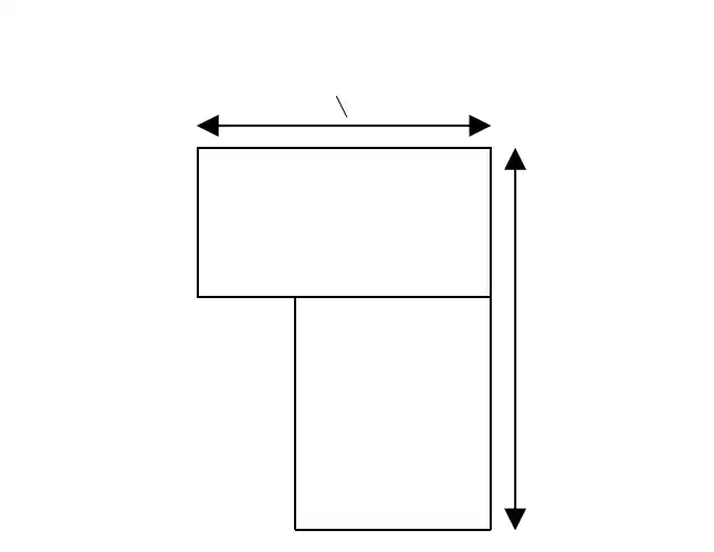
Note: all new installation sites should be checked to ensure that there is room to move this largest module into position
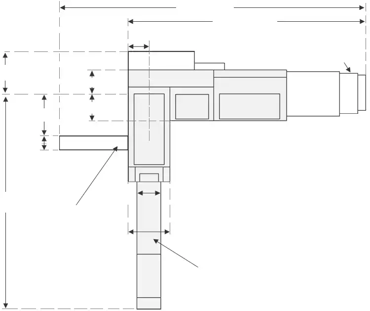
Sheets must be delivered into the Smart-binder infeed from the upstream equipment correctly oriented (usually long edge leading) and with the sheet fold line (normally the center of the sheet) offset from the Smart-binder center-line as shown below.
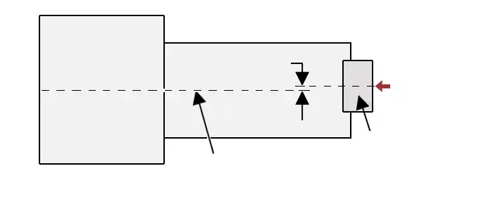
Note: if changing web width when using Smart-binder fed from a web-cutter then the new web must be centralized in the web-cutter.
The Smart-binder infeed accepts sheets delivered from the upstream equipment (or the pile feeder in the off-line configuration) at the following heights.
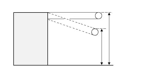
The height of the Smart-binder delivery conveyor at the take-off end is 730mm. A special modified delivery conveyor may be provided if books need to exit at a different height for interface to downstream equipment such as a book stacker or inserter (refer to IBIS for details).
These can be found in the Smart-binder PC controller D: drive. A new file is created every time operating software starts and called ‘LogNNNN.txt’ where NNNN sequential number. Files are limited to about 1 Mbyte started when this limit reached. Logfiles deleted automatically they 100 days old.
Connect to the network port (Smart-binder supports 10/100) on the PC card (upper left of the control panel at back of machine). The log files are on the Hard disk drive (if fitted) drive letter D: (or if you do not have a Hard disk drive they will be in c:\temp). Share the folder (C:\temp or D:)to be able to see it over the network. The Smart-binder runs on a stripped-down version of windowsXP so you do not have the full range of menus, however, you can create a share on a folder by right-clicking the appropriate folder with a mouse.
The optional Smart-Data analysis system SDA-100 assists connection to an external network. See IBIS document Smartbinder_Diagnostics for further information.
When planning installation and commissioning allow 2 days to install the Smart-binder and approximately 8 days for system commissioning and operator training, prior to the start of live production (this time may be reduced if installing an off-line Smart-binder fed from sheet feeder). Allow some extra days for commissioning systems which include optional modules such as F-100, SB-097, BSS-10 and LT-101. For exam paper production lines with full in-line stacking wrapping and labelling systems allow up to two additional weeks before starting live production.
| Day | Activity |
|---|---|
| 1 | Unpacking, checking shipment and moving into position |
| 2 | Assembling Smart-binder, connecting power |
| 3-6 | Commissioning: requires printed work and covers available from day 3 |
| 7-10 | Operator training |
| 11-12 | Pre-production tests |
Note: In particular connection of power (day 2), the availability of printed work (day 3) and the availability of trainees (days 7-10) are critical to meeting this schedule.
Two 2.5K (5.5lbs.) (5 lb) spools of wire are supplied with each Smart-binder, enough for 43,000 to 60,000 stitches from each head (depending on book thickness – thin books need slightly less wire per book than thick books). This is sufficient for normal system commissioning after initial new machine installation.
Other sizes of wire spool (up to 100Kg/220lbs) are available; refer to IBIS for more information.
A suitable wire vendor should be found to provide good quality round cross section wire between 0.4 and 0.6mm in diameter (or wire may be purchased from IBIS).
Smart-binder SB-3s (and most SLBs) are fitted with the ISG glue system and supplied with 5 litres of cold glue, which is sufficient for the normal machine commissioning period. The normal recommended glue is Pafra PVA cold glue AQUAPAL 9278 (sold also by Robatech as R-5183L50), but alternative glues may sometimes be used for difficult applications, such as with the use of coated paper stocks. It is essential that only glues approved by IBIS with the correct viscosity are used to avoid glue application problems.
The Smart-binder uses approximately one litre of ISG cold-glue for every 78,000 sheets (312,000 pages) when applying ‘dots’ of glue at normal spacing. When calculating glue usage per booklet note that:
Wire stitching
The cost of wire to produce 1000 wire-stitched booklets is about GB Pounds £0.74 (price in 2020) if purchased from IBIS. This cost may be lower if buying from a local supplier. The cost does not vary much between a thin and a thick booklet.
ISG cold gluing
The cost of ISG cold-glue binding depends on the number of sheets in the booklet. The cost of Eukalin cold-glue (specification R5183-L50) needed to produce 1000 A4 booklets is as follows (assuming glue purchased from the glue manufacturer):
| Number of sheets in booklet | Number of pages in booklet | Cost of ISG for 1000 A4 books in GB pounds (2020 prices) | |
|---|---|---|---|
| 4 | 16 | £0.08 | |
| 10 | 40 | £0.26 | |
| 30 | 120 | £0.82 | |
Note 1: In summary ISG glue is a lower cost compared with wire staples when making A4 booklets containing up to about 100 pages in thickness or A5 booklets up to about 140 pages (assuming glue purchased directly from the glue manufacturer).
Note 2: If the booklets are A5 size then the cost of glue shown above is reduced by 30%.
Note 3: The ISG cold glue system is easier and less expensive to maintain than the wire stitching system. Also, ISG glued booklets are stronger and lay flatter than wire stapled booklets.
Knives will require sharpening at intervals depending on machine usage and type of booklets being produced (these intervals are normally at least some weeks and often many months). Sharpening is best carried out by a local specialist. For budgeting purposes, assume knives are reground quarterly and replaced with new annually.
Knives must only be changed or adjusted by a trained technician. IBIS provides this training as part of the 5-day Smart-binder service engineer maintenance training course.
Knives are used in pairs consisting of an upper shear knife and a lower bed knife (pairs are not matched: any new or reground upper shear knife may be used with any new or reground bed knife). If one of the pair is changed, the other should also be changed, otherwise premature wear of the new knife will occur.
The same knives are used in the three main knife positions: a complete set of main knives is made up of 3 pairs of shear and bed knives.
The center-knife assembly CKN-100 or 101 consists of a special shear knife, with two cutting edges, and a pair of bed knives (see Appendix 15). Alternatively option CKN-102 has a singled bladed upper knife and only one lower knife. As with other knives, these should be treated as a set, and all be changed together.
We recommend that at least two sets of knives are purchased in addition to the set supplied with the machine. This allows for one set to be in use on the machine, one set to be away for regrinding and one set ready to install in case the knives in use are damaged.
One spare set of knives is included in the basic spares kits; additional sets can be purchased from IBIS